
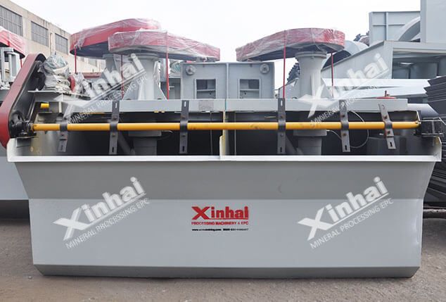
【Product Introduction】:An air inflation mechanical agitation Flotation Cell with slurry suction(as suction cell of KYF flotation cell).
【Applicable Materials】:Non-ferrous metals, ferrous metals, and non-metallic minerals
【Production Capacity】:0.2~38 m³/min
【Product Application】:XCF type flotation machine is suitable for roughing and sweeping operations in large and medium-sized flotation plants

It can be combined with KYF flotation machine to form a combined flotation unit as a suction tank;
The structural features and performance of the XCF flotation machine are similar to those of the KYF flotation machine. The difference is that a stator is specially arranged above the impeller to form a special negative pressure zone and self-absorb the pulp. In the flotation process, rational use of flotation reagents can more effectively separate useful minerals and gangue minerals.
The working principle of the XCF flotation machine is mainly to drive the impeller to rotate through the motor transmission device and the hollow main shaft. The slurry in the tank is sucked into the lower blades of the impeller through the bottom of the tank through the inner edge of the lower blades of the impeller. At the same time, the low-pressure air supplied from the outside enters the air distribution of the lower impeller cavity through the beam, air regulating valve, and hollow main shaft. Then, through the small holes around the air distributor, it enters between the lower blades of the impeller. After the pulp and air are fully mixed between the lower blades of the impeller, they are discharged from the outer edge of the lower blades of the impeller.
Due to the joint action of the rotation of the flotation machine impeller, the cover plate and the central tube, a certain negative pressure is generated in the upper blade of the impeller, so that the medium ore foam and the ore feed through the medium ore pipe and the ore pipe flow into the central barrel. , And enter between the upper blades of the impeller, and finally discharge from the outer edge of the upper blade. The mixture of ore pulp and air discharged from the outer edge of the lower blade of the impeller and the medium ore and feed ore discharged from the outer edge of the upper blade of the impeller are steadily flowed and oriented by the stator installed around the impeller, and then enters the main ore slurry in the tank, and the mineralized bubbles rise to A foam layer is formed on the surface of the slurry. A part of the slurry returns to the lower blades of the impeller for recycling, and the other part enters the next tank through the flow holes on the wall between the tanks for re-selection or discharge as a final product.
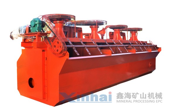
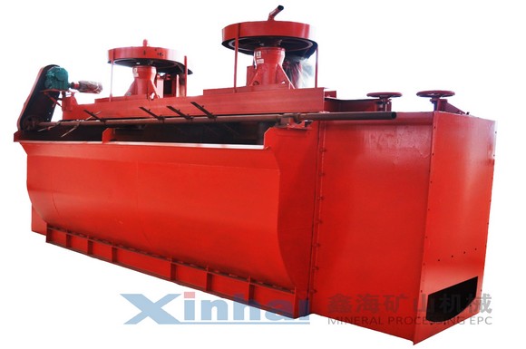
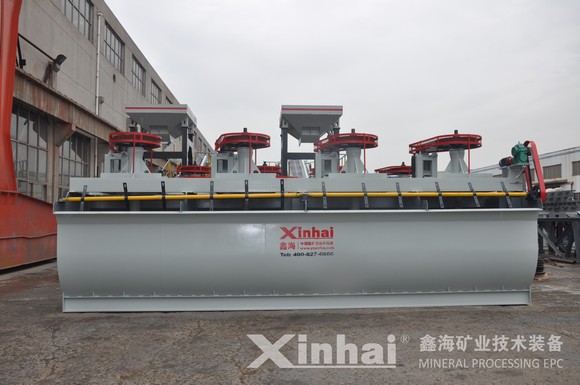
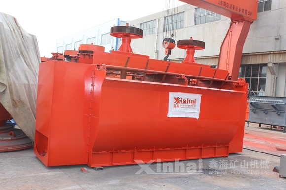
The air-filled flotation machine is difficult to absorb slurry due to the entry of low-pressure air, which reduces the negative pressure in the central area of the impeller. The discs are separated, each has its own function, and does not interfere with each other. The upper blade of the impeller is only responsible for sucking the slurry, and the lower blade is responsible for circulating the pulp and dispersing the air. The lower blade of the impeller adopts the shape of the impeller similar to the KYF flotation machine, which ensures that the newly developed slurry suction flotation machine has the good separation process performance of the KYF flotation machine, and at the same time ensures that the aeration method is the same as the KYF flotation machine. , That is, low-pressure air is pressed into the air distributor at the center of the lower blade of the impeller through the hollow shaft, and then enters between the lower blades of the impeller to mix with the slurry, so that the two flotation models are very similar, and the number of different parts is reduced to least. The upper blade adopts radial and straight blades, and there is no interference of external aeration in the central area of the upper blade, which can form a relatively large negative pressure to suck the slurry.
| Model | effective volume (m3) | Processing capacity (m3/min) | Impeller diameter (mm) | Impeller speed (r/min) | Air pressure of blower (kPa) | Maximum inflation (m3/m2-min) | Motor power for mixing (kW) | Motor power for scraper (kW) | weight (kg) |
|---|---|---|---|---|---|---|---|---|---|
| XCF-1 | 1 | 0.2~1 | 400 | 358 | > 12.6 | 2 | 5.5 | 0.75 | 1154 |
| XCF-2 | 2 | 0.4~2 | 470 | 305 | > 14.7 | 2 | 7.5 | 1.1 | 1659 |
| XCF-3 | 3 | 0.6~3 | 540 | 266 | > 19.8 | 2 | 11 | 1.5 | 2259 |
| XCF-4 | 4 | 1.2~4 | 620 | 225 | > 19.8 | 2 | 15 | 1.5 | 2669 |
| XCF-8 | 8 | 3.0~8 | 720 | 175 | > 21.6 | 2 | 22 | 1.5 | 3868 |
| XCF-10 | 10 | 4~10 | 720 | 192 | > 21.6 | 2 | 30 | 1.5 | 4800 |
| XCF-16 | 16 | 4~16 | 860 | 160 | > 25.5 | 2 | 37 | 1.5 | 6520 |
| XCF-24 | 24 | 4~24 | 950 | 153 | > 30.4 | 2 | 37 | 1.5 | 8000 |
| XCF-38 | 38 | 10 ~38 | 1050 | 136 | > 34.3 | 2 | 55 | 1.5 | 11000 |

An air inflation mechanical agitation Flotation Cell with slurry suction(as suction cell of KYF flotation cell).
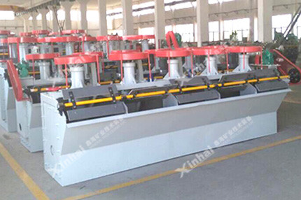
The BF flotation machine is a self-aspirated mechanical agitation flotation unit with combined slurry suction/non-slurry suction.
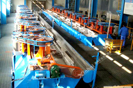
SF flotation cell is a mechanical agitation type with slurry suction and air suction.
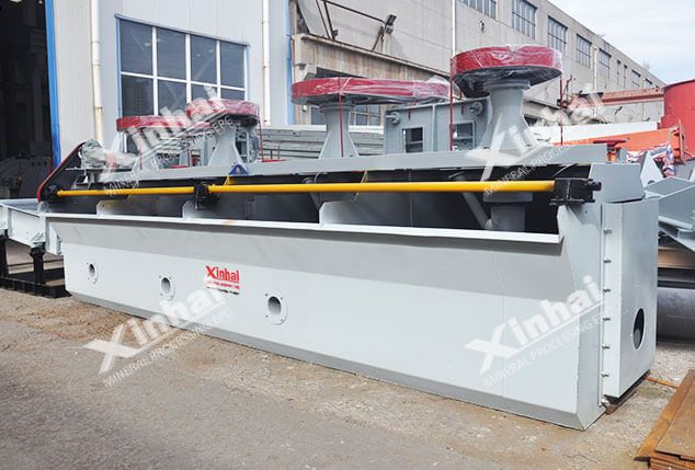
JJF flotation cell is a air self-suction mechanical stirring floatation cell without slurry suction (Referring to the design of USA wemco flotation machine)

An air-inflation mechanical agitation flotation cell without slurry suction (This type of cell is designed referring to Finland Autoquenpu OK flotation cell).
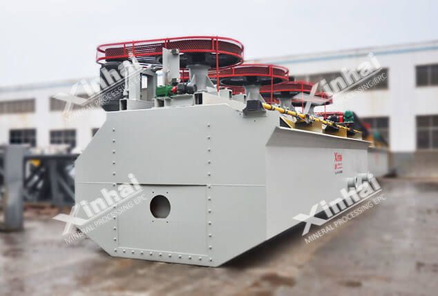
A bar flotation cell with self-air suction and mechanical agitation
A flotation cell used for coarse and heavy particles.